Data acquisition
| Highlights |
|---|
|
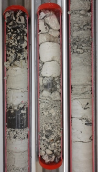
ContentsGeology and hydrogeologyKnowledge about geology and hydrogeology of a contaminated site is usually limited and not easily obtainable. This page gives a description of some useful methods to determine relevant aquifer parameters and to characterize the fracture system. Information about the geology and hydrogeology at a site is primarily obtained from locations that provide access to the subsurface, such as outcrops, excavations and boreholes, and from geophysical measurements. The Danish national well database (Jupiter) contains very useful borehole information, such as the location of boreholes, the geology in the boreholes, groundwater analyses, and information about water supply wells. This can be combined with information from geologic maps and interpretations, as, for example, provided by the Geological Survey of Denmark and Greenland. Borehole cores and borehole testsA common method to obtain knowledge about the local geology is to drill boreholes, collect borehole cores (Figure 1) and perform (geophysical) borehole tests. However, one has to bear in mind that cores only represent the geology at the location of the borehole and that the geology can have a strong spatial variability. The information obtained from cores from different boreholes can be spatially interpreted and combined with geologic knowledge from maps to build up a geologic model. Collected borehole cores can be analyzed (e.g. determination of porosity and hydraulic conductivity) and the depth-discrete stratigraphy at the location of the borehole can be determined. With a microfossil analysis, the age and the type of limestone can be further characterized. However, in limestone geologies with flint layers and a strongly varying hardness with depth, core losses may be significant (Figure 2), and thereby alternative borehole and aquifer tests needed to characterize these areas. At the Akacievej site, several borehole cores were extracted, and microfossil analyses were conducted to determine the limestone type. The limestone had a strongly varying hardness. Thus, losses of especially the crushed material were considerable, despite the use of wireline drilling, which is a good coring method in limestone as the geology is only little disturbed by the drilling. Especially when drilling through flint inclusions, substantial core losses were observed (Figure 2), because the cooling water flushed out soft material. The boreholes, where no cores were extracted, were drilled with different methods: dry drilling (tørboring), symmetrix and DTH drilling. The borehole tests at the Akacievej site included:
Aquifer testsPumping testsPumping tests are very useful to characterize the local hydrogeology at a contaminated site. Usually, a well is pumped and the drawdown behavior (hydraulic head changes) in the pumping well and (if available) in neighboring observation wells are measured. This can be done with manual head measurements, if the hydraulic head changes happen relatively slow. Fractured aquifers, however, often exhibit a high hydraulic conductivity and the drawdown happens quickly, which makes it difficult to manually measure the drawdown caused by the pumping. In this case, the head changes can be monitored with programmable pressure transducers (divers), which measure the hydraulic heads at a high measurement frequency. Two measurements per seconds or even more are recommended for fracture-flow dominated aquifers or aquifers with a high hydraulic conductivity. The drawdown curves can be interpreted with a suitable tool (e.g. Aqtesolv), which allows the determination of aquifer parameters like the hydraulic conductivity. In fractured aquifers, long-term pumping tests with a high pumping rate can potentially reveal information about the hydraulic conditions in both fractures and matrix. Drawdown curves from long-term pumping tests in fractured limestone aquifers exhibit different stages - first, pumped water is mainly withdrawn from the fractures, followed by a stage with fracture-matrix interflow, and in the last stage, the water is mainly abstracted from the matrix. At the Akacievej site, the full drawdown had developed within a time period of about 10 days. For the interpretation of such drawdown curves, specialized dual-continuum solution schemes (e.g. the dual-porosity solution presented in Moench, 1984 [1] or Barker, 1988 [2]) can be employed. However, it has to be kept in mind that the obtained values only describe the area affected by the pumping test and an extrapolation has to be done with care, especially if the aquifer is very heterogeneous. A higher pumping rate can potentially enlarge the affected area. Further, in screened wells, the (vertical) location of the screen is important, since water is mainly pumped from the part of the aquifer at the depth of the screen (or in case of an open borehole, of the open section of the borehole). Packers can be installed to separate sections of the aquifer and to determine hydraulic conductivities (or transmissivities) for these sections. The following report contains a detailed description of a long-term pumping test that was conducted at the Akacievej site in combination with six tracer tests and PCE measurements: Slug testsSlug tests are relatively cheap and easy single-borehole aquifer tests, where the water table in a borehole is abruptly changed, for example, by releasing a slug of water into the borehole while monitoring the pressure response, when the water table changes back to its original state again. They can be used to obtain approximate values of the hydraulic conductivities at the location of a borehole. Therefore, the hydraulic head has to be measured with a high frequency. In low conductivity aquifers, this can be done with manual measurements using common dip-meters. In highly conductive aquifers, the water table responds quickly, and automated measurements with pressure transducers should be chosen. These pressure transducers should be set to a sufficiently small time interval (ideally several measurements per second). There are different types of slug tests. A main distinction can be made between rising-head slug tests and falling-head slug tests.
To perform a rising-head slug test, water is removed from the borehole and the recovery of the hydraulic head in the borehole is recorded. This can be a good choice for aquifers with moderate flow velocities but can be problematic for highly conductive aquifers.
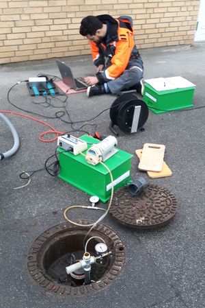
For a falling-head slug test, the water level in the borehole is abruptly increased. This can be done on different ways. A slug of water can be added into the borehole and the head change monitored. For aquifers with a high hydraulic conductivity, a different method is recommended: A vacuum is applied on the borehole to pull the water table up at the borehole (Figure 4). The raised water table is then released and the equilibration of the water table measured with pressure transducers with a short measurement interval (several measurements per second). This method was particularly useful for slug tests in the highly conductive fractured limestone at the Akacievej site. The interpretation of slug tests with standard aquifer test software like Aqtesolv allows for obtaining information about the local hydraulic conductivity. For fractured aquifers, a solution scheme that is accounting for the fractures and the dual-porosity aquifers like the Barker-Black (1983) solution can be chosen. In very conductive aquifers, an oscillating water table caused by inertia can occur when the slug is released. There are specialized solution schemes (f.e. the solution by Springer and Gelhar (1991)[3]), which can be applied then. Note that slug tests are very local measurements, because they usually affect only a small volume around a borehole and an extrapolation of the determined parameters should be done with care. Furthermore, the slug test results can be influenced by the borehole filling (gravel or sand pack around the well screens). If several boreholes are close by or if there are boreholes with several well screens at different depth, slug tests can yield information about the local variability of the hydraulic conductivity. Slug tests at different depths can yield hydraulic parameters for different geologic units. Additional information from water works data and remediation systemsWaterworks can provide a cheap and simple way for getting additional pumping test data. Waterworks are operating one or several wells, where often automated loggers are installed, which monitor the hydraulic heads in the pumped wells. When the pumps are switched on and off, drawdown and recovery curves can be obtained, which can be analyzed with standard aquifer test software (e.g. Aqtesolv) like usual pumping tests. To obtain data useful for interpretation, a high measurement frequency should be set for the hydraulic head logging in the wells, particularly for aquifers with a high hydraulic conductivity. For highly conductive aquifers like the one at Akacievej, a good choice of the measurement interval is 1 second or less. The Fløng waterworks close to the Akacievej site operates an alternating pumping scheme in four drinking water wells, where the individual wells are automatically switched on and off according to the water demand. This creates a sequence of pumping-test like events, which were evaluated to obtain the hydraulic conductivity at the wells of the water works. Note that the wells used by the water works have often long screens, and that the measurements represent average values over the screen length or borehole length (in case of an open borehole). Furthermore, head measurements from a remediation system can be interpreted to obtain hydraulic parameters at the location of the remediation system. At the Akacievej site, the remediation system was turned on and off several times, and the hydraulic heads in the remediation well and in observation wells next to it were measured. This information was used to calibrate a flow model to the observed drawdown and to get more information about the crushed limestone, where most of the screen of the remediation well is located in. Fracture characterizationIn fractured limestone aquifers, the fractures are the primary travel pathways for substances, and their characterization is important for risk assessment and remedial planning. Information about the fracture geometry and location is, however, generally scarce and the determination of appropriate parameters may be challenging. Fractures are generally described by their aperture, spacing, distribution, length, height and their main orientation. The flow and transport in fractures is furthermore controlled by the fracture connectivity. The following measurements are useful to determine fracture parameters:
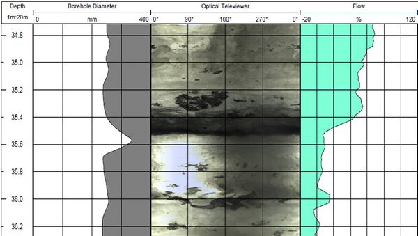
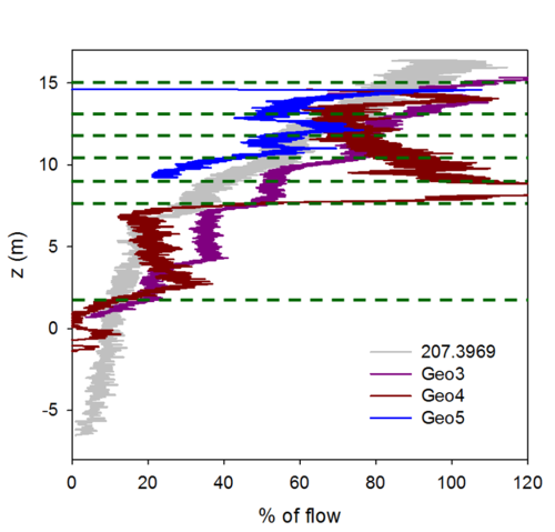
Flow logs in boreholes can be very useful to identify highly conductive zones (Figure 6). Therefore, a propeller probe is lowered in the borehole and the speed of the propeller rotation is recorded while pumping the borehole. The propeller probe is slowly moved up- or downwards. High-flow zones will lead to a change of the propeller rotation speed and high-flow zones can be identified from the logs. For this method, even borehole walls are beneficial. Holes or gaps in the borehole walls can lead to disturbances in the flow logs due to local turbulences and backflow of water. When the propeller probe is used without pumping, some information about vertical flows in the boreholes can be obtained. When open boreholes (without well screen) are available, FLUTe liners can be used to identify high-flow zones. Moreover, optical and acoustical televiewers can be used to take images of the borehole walls. With vertical boreholes, mainly horizontal fractures and flint layers can be identified by this method. For the determination of vertical fractures, diagonal boreholes can be beneficial, because they increases the likelihood that vertical fractures intersect with the borehole. A sample image from a vertical borehole at the Akacievej site (Geo18d) is shown in Figure 5. The dark area at a depth of 35.4 m below ground surface is a significant horizontal fracture. This is reflected in the flow log in the right part of Figure 5. At the same depth as the dark area, a strong change in the flow log can be observed. This is an indication for a high-flow zone. |
- ↑ Moench, A.F. (1984), Double-porosity models for a fissured groundwater aquifer with fractures skin, Water resources research, Vol.20, 831-846.
- ↑ Barker, J.A. (1988), A generalized radial flow model for hydraulic tests in fractured rock, Water resources research, Vol.24, 1796-1804.
- ↑ Springer, R. and Gelhar, L. (1991), Characterization of large-scale aquifer heterogeneity in glacial outwash by analysis of slug tests with oscillatory response, Report, U.S. Geological Survey.


