Example: Akacievej
Example: Setup and application of models for a field site (Akacievej, Hedehusene)
Several models were compared for the Akacievej site, where a plume of dissolved PCE had spread in a fractured limestone aquifer and where a remediation system was in the process of re-evaluation. Numerical modeling was integrated in the planning of new field tests and in the update of the conceptual model of the contaminated site, starting from a simple model and adding complexity, when new field data was available.
The field data included information on spill history, hydraulic head data, well data (location, screen depth etc.), distribution of the contaminant (multilevel sampling), geology and hydrogeology. To describe the geology and fracture system, data from borehole logs, packer tests, optical televiewers and cores were combined with an analysis of local heterogeneities and data from analogue sites. A pumping and tracer test was conducted at the site to determine flow and transport parameters of the fractures and matrix and depth-specific contaminant sampling allowed to characterize the contaminant distribution in the aquifer. For the planning and interpretation of the pumping and tracer test models of different complexity were applied. This is described in detail in the following report:
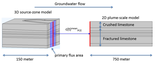
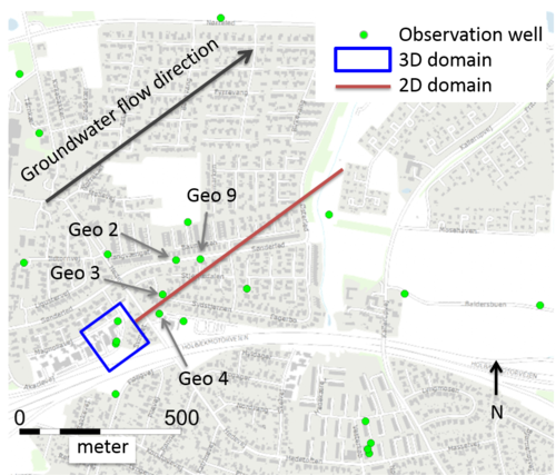
In 2018, the the hydraulic heads were again measured in the plume area, which showed that the flow conditions were fairly constant since the hydraulic head leveling campaign in spring 2015. The picture of the PCE distribution was updated by depth-specific measurements in the source- and plume area using a bladder pump. To reduce the numerical effort and to simulate the plume propagation on a larger scale, a 3D source-zone model coupled to a 2D plume-scale model was developed. The 3D model resolves flow and transport in the source zone. Therefore, an initial contaminant distribution in the source zone was implemented, which is based on depth-specific measurements of PCE in the monitoring wells at the Akacievej site. The source-zone model was calibrated to the long-term pumping and tracer test and then used to compute the contaminant input fluxes for the 2D model, which starts at the downstream end of the source zone model (Figure 1).
The following report (in Danish) shows the setup and application of this coupled 3D source-zone and 2D plume-scale model, which supported the re-evaluation of the remediation system at the Akacievej site:
Since the depth-discrete contaminant sampling showed that a great part of the PCE contamination is located in the crushed limestone (upper 3-5 m), the crushed limestone was included in the model setup as a separate layer with different properties as the fractured limestone. The bulk hydraulic conductivity was slightly lower than in the fractured limestone, and no distinct horizontal fractures as in the fractured limestone could be identified. Detailed investigations of the properties were very difficult for the crushed limestone, because due to its crushed state it is very unstable and core material was mostly lost. The characterization of the hydraulic properties was based on slug tests in wells that have a screen mostly in the crushed limestone and by evaluating the drawdown caused by the remediation pump installed at the Akacievej, which is also mostly located in the crushed limestone. Most likely, the fractured limestone contains many more small fractures, small cavities and some larger intact limestone chunks.
Then, most of the advective transport happens in the conductive areas with a diffusive exchange with lower conductive (immobile) areas. This could be described by a dual-porosity model. However, there was only limited knowledge of the hydraulic properties in the high- and low-conductive areas and the exchange between them. Instead, a homogeneous unit with a uniform conductivity was used. To still account for the contaminant mass exchange with the immobile areas, the sorption coefficient was increased. This is further explained in the report linked above.

