Transport parameters and contaminant data
| Highlights |
|---|
|
Transport parametersAdvective transport happens with the groundwater flow. However, to describe the transport of a substance in a fractured limestone aquifer properly, additional parameters are required. Important transport parameters that influence the migration of a substance are
Tracer tests are very useful to analyze the transport behavior in a limestone aquifer. Different types of tracer tests can be distinguished:
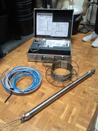
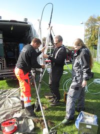
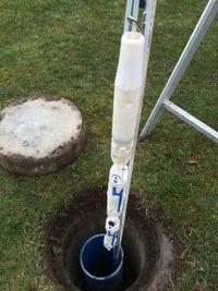
In the limestone project, a forced-gradient tracer test with several injection wells and a central pumping well for tracer monitoring was conducted. Details are described in the following report: Furthermore, measurements from core material can be used to determine the porosity and hydraulic conductivity of a limestone sample, for example using gas permeameter and porosimeter (Poroperm test). At the Akacievej site, this yielded porosity values between 7 and 46 %, with a strong variation with depth. The determined hydraulic conductivity values were correlated to the porosity (and limestone hardness) and were in the range of between 5x10-11 and 10-6 m/s, see [1]. Sampling methods to determine contaminant dataDifferent sampling and monitoring techniques to determine the depth-discrete contaminant distribution in boreholes have been developed. Depth-discrete sampling is important, since the very heterogeneous nature of the aquifer can result in strong concentration variations over depth. For the planning of a site remediation it is important to know the vertical extent and the location of the contamination, so the remediation system can be planned most effectively. One way to obtain depth-discrete concentrations is to analyze small samples from borehole cores for the contaminant concentration (Figure 1). However, limestone has a very varying hardness and may be unstable. This complicates the collection of representative samples as well as the subsampling of the collected cores in the laboratory. Soft limestone material is often lost when extracting a borehole core. The concentration in the softer, more porous material is thereby not represented and as a consequence, the core analysis may lead to inadequate vertical delineation of the contaminant distribution. In situations where larger areas of the subsurface (e.g. the crushed zone) is lost during coring, the lack of data could lead to a wrong conceptual model. Depth-discrete concentrations can also be obtained by water sampling in the borehole. Water sampling is a good supplement to the core sampling, especially in depths intervals with high core losses or when a temporal development in the concentrations needs to be monitored. The sampling is done best from dedicated multilevel screens; however, this is not always an option, especially in unstable limestone. Water sampling is generally divided into active and passive sampling methods. Active water sampling is based on the assumption that the water at the well screen is not representative due to mixing or other processes in the well, whereby purging is needed. However, the active pumping may draw in water from other formation layers not representing the specific depth. Low-purge sampling tries to accommodate this by utilizing a slow-flow for limited purging, this method may be considered semi-passive at very low flow rates. The passive sampling is based on the assumption that the flow is horizontal and laminar at the screen, whereby the most representative data is achieved by a minimum disturbance of the flow. However, this flow assumption may not always be valid and the (semi-)passive methods are vulnerable to e.g. vertical flow in the well. The following sampling methods were utilized at the long screened wells at the Akacievej site:
The snap samplers and bladder pump were found to give comparable results, while lower concentrations were generally found with the separation pumping (likely due to dilution with less contaminated water from greater distances). Diffusion cells (passive sampling, equilibrium) were also tested. Initially the diffusion properties (equilibrium time etc.) were determined in the lab, however, these properties were not transferable to the field resulting in concentrations that varied significantly from the other (semi-)passive methods. The following report gives a more detailed comparison of these sampling methods. Additional sampling methods that require open (unscreened) boreholes include:
|
- ↑ Broholm et al. (2016a), Sammenligning af niveauspecifikke prøvetagningsmetoder for vurdering af koncentrationsfordeling i kalkmagasin. DTU Environment
- ↑ Broholm et al. (2016b), Characterization of chlorinated solvent contamination in limestone using innovative FLUTe technologies in combination with other methods in a line of evidence approach, Journal of Contaminant Hydrology 189, 68-85


